Unboxing the DJI NAZA-M Light

Finally got the DJI NAZA-M Light I ordered. It did get delayed - came about 2 weeks after the expected delivery date, which I'm guessing was due to the holiday season. But finally since it arrived, I wasted no time on unboxing it.

The NAZA-M Light came in a neat little box
It came packed in a pretty nice box. I was actually expecting 2 boxes, since I ordered the GPS unit as well. But it turns out the GPS Unit box comes inside the main DJI NAZA box.
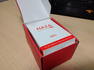
The GPS unit fits nicely inside the main package
So, let's unpack everything and see what we got.
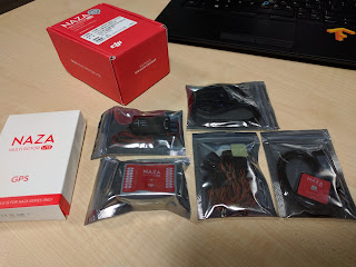


Everything unpacked
Everything unpacked
First up, is the control module, a.k.a. the flight controller. This is the heart of NAZA. Every aspect of the multicopter is controlled by this.

The Flight Controller Module
Next up, is the power regulator. This powers the flight controller from the battery.

The power regulator
The power regulator
Next, we got the LED module, which works both as an indicator of the state of the multicopte, and has the ports to connect your NAZA to the PC.
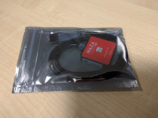
The LED Module
The LED Module

Then, we have some wires and connectors...
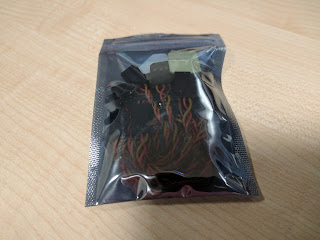
Wires and connectors
 ... and the USB cable, which connects through the LED module.

The USB cable
The USB cable

Moving over to the GPS module box, we have the GPS module, and the standoffs to mount it.

The GPS module, and mounting bits

Now I'm eagerly waiting for the F550 frame to come, so that I can start building my hexacoptor.

Comments

Popular posts from this blog

Selecting the Correct Gauge Wires for your RC Models

When we are building RC models (aircrafts, multicopters etc.), something we typically overlook is what type of wires to use to distribute power in them. Usually, we try to reduce the weight of the model, so we tend to go with smaller wires. But, we cant expect to put in small circuit-wires and have them handle the amount of power needed. If you look at the wires that comes in the output leads of a Li-Po, or the wires that comes on a standard XT Jack, you'll notice that they're quite huge. Large gauge wires on a Li-Po and XT connectors These need to be huge to handle the amount of amperage that goes through them. So, we should also consider the amperage, and the length of wire needed when selecting the size (gauge) of the wires.

What do the prop size numbers mean?

Have you been trying to shop for propellers - either online or at a hobby shop - and got confused of the numbering used to denote the size of the propellers? You see things like " 10 x 4.5 CW ", or " 8055 CCW ". What do these numbers mean? A 8 x 4.5 CW and CCW Propeller Set It's actually quite simple once you figure it out. The first number denotes the diameter of the prop (length from tip-to-tip). The second number denotes the pitch of the prop. Here, the pitch is denoted as a length, not a angle. Let's see how that works.

Make Your Own Jupmer Wires for Electronic Breadboard

Note: After starting the 'Tips and Tricks' section I wanted to do my own 'tutorial'. So, here's my first attempt of it. Hope you all find this useful, and sorry about the low quality of the photographs, my camera is just a 2MP. If you, like me, like to experiment with electronics, then you'd probably use an electronic breadboard (also known as protoboard or project-board). These allow you to construct and test circuits without the need to permanently soldering the components. The problem with these is that you have to use wires to connect the components across the bus lines. We normally use single core circuit wires for this purpose, but they tend to bend, break and get stuck in the breadboard when used repeatedly. This may cause short circuiting the bus lines and could be the failure of your circuit. A better option would be to buy a 'Breadboard Jumper Wire' kit, such as this. A Breadboard Jumper Wire Kit These have sets of wire of differ...