It's been over 2 months since I posted the first post on building a quadcopter (link). You would've thought that I must have completed the build by now. But actually, I couldn't do much. Mainly because that my transmitter shipment got late.
As you remember, I ordered a HK-T6Av2 from HobbyKing (link) (Actually, a friend ordered it for me as a gift). It was shipped on 21st March. Usually takes less than a month to arrive. But since I didn't receive it until 25th April, I made a complaint to HobbyKing. They said they'd start an investigation on it. On 11th May, the Hong Kong Post mail tracking reported that the parcel was returned to sender. Why was it returned? no one knows...
Anyway, I contacted HobbyKing again and they said they can arrange it to be resent once it reaches their warehouse. The parcel reached them on 25th May and it was re-shipped on 31st. It finally arrived about a week ago....
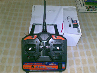
So, here it is...
I have to say, even though it has been through a transit of two months, it was in perfect working order.
The package contained all that was stated, Transmitter, Receiver and the Bind Plug.
Now, the first thing to do was to 'bind' the receiver to the transmitter. Usually, the receiver that comes with the transmitter is already bind. But it's always better to bind it again, just in case.
Here is the binding procedure
Here's how to plug the bind plug
And here's the pinout of the receiver
I found the Manual for the transmitter. Download it from this link - HK-T6 Manual
I still haven't ordered the USB cable for the transmitter, so can't test any config functions. But now that I got this, it's time to go ahead with the quad build.
I would like to give special thanks to my good friend Anushka Perera for this awesome gift. Thank you :)
As you remember, I ordered a HK-T6Av2 from HobbyKing (link) (Actually, a friend ordered it for me as a gift). It was shipped on 21st March. Usually takes less than a month to arrive. But since I didn't receive it until 25th April, I made a complaint to HobbyKing. They said they'd start an investigation on it. On 11th May, the Hong Kong Post mail tracking reported that the parcel was returned to sender. Why was it returned? no one knows...
Anyway, I contacted HobbyKing again and they said they can arrange it to be resent once it reaches their warehouse. The parcel reached them on 25th May and it was re-shipped on 31st. It finally arrived about a week ago....
So, here it is...
 |
| It's finally arrived... |
I have to say, even though it has been through a transit of two months, it was in perfect working order.
The package contained all that was stated, Transmitter, Receiver and the Bind Plug.
 |
| Receiver and the Bind Plug |
Here is the binding procedure
- Install the batteries to the transmitter. Don't turn on yet
- Install the bind plug to the Bat port of the receiver
- Give power to the receiver through any of the other ports. It's better to provide power through an ESC because it's regulated. The receiver LED bill start blinking meaning it's going in to bind mode.
- Press and hold the Bind Button of the transmitter and switch it on
- Observe the receiver LED. When it stops blinking, the bind was successful (Note: the manual says it can take up to 10 seconds for the bind. mine took about 2 seconds)
- Release the bind button on the transmitter and remove the bind plug and the battery from receiver.
- Connect a servo and power on the receiver again and test if it's working.
- If the test fails, repeat 1-7.
Here's how to plug the bind plug
 |
| How to install the bind plug |
And here's the pinout of the receiver
 |
| Receiver pinout (Signal, +, -) |
I found the Manual for the transmitter. Download it from this link - HK-T6 Manual
I still haven't ordered the USB cable for the transmitter, so can't test any config functions. But now that I got this, it's time to go ahead with the quad build.
I would like to give special thanks to my good friend Anushka Perera for this awesome gift. Thank you :)
Comments
Post a Comment